
자이로 센서와 프로세싱으로 나침반 만들기
2016-05-03 16:25:33
개요
자이로 센서의 종류에는 3축, 6축, 9축이 있고 각 축의 자이로 값을 구할수도 있고 가속도 센서의 값 또한 구할 수 있습니다.
자이로 값을 변형한다면 나침반을 만들어 볼 수 있습니다.

나침반은 한번씩 보고 써봤을텐데 현재 위치에서 동, 서, 남, 북의 위치를 알려주는 도구입니다.
나침반은 지구의 자기성을 이용하여 방위를 측정하는 자기 나침반과 지구의 자전성을 이용하여 자이로를 통해 방위를 측정하는 자이로 나침반이 있습니다.
자이로 나침반은 자기 나침반처럼 지구의 극성을 이용하지 않고 자전성을 이용하여 자전축을 찾아 북쪽을 가르키게 됩니다.
이번 글에서 이용할 자이로센서에서는 X축, Y축, Z축 자이로값을 구할 수 있기 때문에 자이로 나침반을 구현해 볼 수 있습니다.
필요한 부품 목록
|
NO |
부품명 |
수량 |
상세설명 |
|
1 |
오렌지 보드 |
1 |
아두이노 우노 호환 |
|
2 |
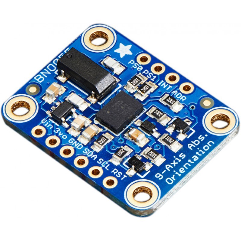
자이로 센서 |
1 |
BNO055 |
|
3 |
점퍼 케이블 |
1 |
|
|
4 |
브레드보드 |
1 |
|
| 부품명 | 브레드보드 | 자이로 센서 | 점퍼케이블 | 브레드 보드 |
| 파트 | 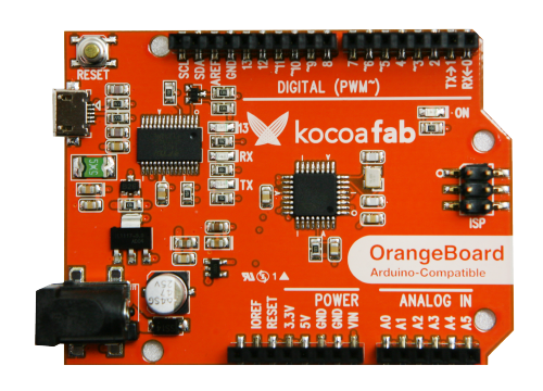 |
 |
 |
 |
※이 프로젝트에서는 Adafruit의 자이로 센서를 사용했지만 꼭 이 센서가 아니더라도 다른 센서로도 코드를 수정하여 충분히 만들어 볼 수 있습니다.
하드웨어 making
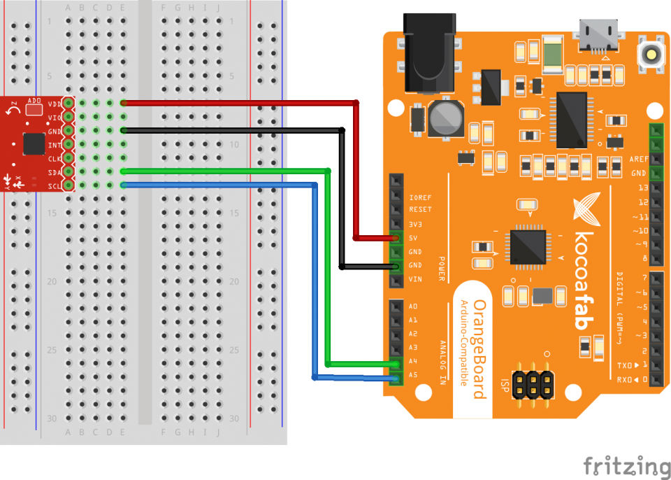
자이로 센서의 VCC(Vin)핀을 아두이노의 5V에 연결합니다.
자이로 센서의 GND핀을 아두이노의 GND에 연결합니다.
자이로 센서의 SDA핀을 아두이노의 A4에 연결합니다.
자이로 센서의 SCL핀을 아두이노의 A5에 연결합니다.
소프트웨어 coding
아두이노 코드
#include <Wire.h>
#include <Adafruit_Sensor.h>
#include <Adafruit_BNO055.h>
#include <utility/imumaths.h>

Adafruit_BNO055 bno = Adafruit_BNO055(55);

float heading, headingDegrees, headingFiltered, declination;

void setup(void) {
	Serial.begin(9600);
	Serial.println("Orientation Sensor Test"); Serial.println("");

	/* Initialise the sensor */
	if(!bno.begin()) {
		/* There was a problem detecting the BNO055 ... check your connections */
		Serial.print("Ooops, no BNO055 detected ... Check your wiring or I2C ADDR!");
		while(1);
	}

	delay(1000);

	bno.setExtCrystalUse(true);
}

void loop(void) {
	sensors_event_t event;
	bno.getEvent(&event);

	imu::Vector<3> euler = bno.getVector(Adafruit_BNO055::VECTOR_EULER);
	//Calculating Heading
	float y = euler.y();
	float z = euler.z();

    //------------------calculate--------------------
	heading = atan2(y, z);

	// Correcting the heading with the declination angle depending on your location
	// You can find your declination angle at: http://www.ngdc.noaa.gov/geomag-web/
	// At my location it's 4.2 degrees => 0.073 rad
	declination = 0.073;
	heading += declination;

	// Correcting when signs are reveresed
	if(heading <0) heading += 2*PI;

	// Correcting due to the addition of the declination angle
	if(heading > 2*PI)heading -= 2*PI;

	headingDegrees = heading * 180/PI; // The heading in Degrees unit

	// Smoothing the output angle / Low pass filter
	headingFiltered = headingFiltered*0.85 + headingDegrees*0.15;

	//Sending the heading value through the Serial Port to Processing IDE
	Serial.println(headingFiltered);

	delay(50);
}
위 코드를 보면 Y축과 Z축의 자이로 값을 받아와서 atan2() 함수로 아크탄젠트값을 받아옵니다.
heading = atan2(y, z);
아래 코드는 현재 내가 있는 곳의 경사의 라디안값을 추가하는 코드입니다.
내가 있는 곳의 기울기가 4.2도 일경우 라디안값으로 변환시 0.073이 되므로 0.073을 더해줍니다.
이 부분은 0으로 바꿔줘도 큰 문제는 없습니다.
declination = 0.073;
heading += declination;
나침반은 0도부터 360까지 전방위를 측정하기 때문에 그냥 파이(180도)가 아닌 2파이(360)까지 값을 측정해야 합니다.
측정된 라디안값이 0보다 작을 경우 2파이를 더하여 0도부터 360도 사이의 값으로 변환시키고
360도를 초과했을 경우 2파이를 빼서 이 역시 0도부터 360도 사이의 값으로 변환시킵니다.
if(heading <0) heading += 2*PI;
if(heading > 2*PI)heading -= 2*PI;
만약 다른센서를 사용하실 경우 아래 코드는 그대로 사용하고 센서 값을 읽어오는 부분만 수정한다면 문제없이 사용할 수 있습니다.
프로세싱 코드
import processing.serial.*;
import java.awt.event.KeyEvent;
import java.io.IOException;

Serial myPort;
PImage imgCompass;
PImage imgCompassArrow;
PImage background;
String data="";
float heading;
void setup() {
  size (1920, 1080, P3D);
  smooth();
  imgCompass = loadImage("Compass.png");
  imgCompassArrow = loadImage("CompassArrow.png");
  background = loadImage("Background.png");

  myPort = new Serial(this, "COM53", 9600); //COM53번과 9600bps속도로 시리얼 통신 시작
  myPort.bufferUntil('\n');
}
void draw() {

  image(background,0, 0); //background 이미지 로딩

  pushMatrix();
  translate(width/2, height/2, 0); //스크린의 중심점을 0,0에서 스크린의 중앙으로 변경한다.
  rotateZ(radians(heading)); //아두이노에서 heading값을 받아 움직인다
  image(imgCompass, -960, -540); //Compass이미지를 로딩한다. translate함수로 스크린 중앙으로 중심점을 옮겼기 때문에 0,0에서 이미지를 띄우기 위해 -960,-540에서 이미지를 로딩한다.
  popMatrix();

  image(imgCompassArrow,0, 0);//CompassArrow이미지 로딩. matrix밖에 있기 때문에 heading값에 영향을 받지 않는다.
  textSize(30);
  text("Heading: " + heading,40,40); //각도값 출력

}
//시리얼통신으로 데이터 수신
 void serialEvent (Serial myPort) {

   data = myPort.readStringUntil('\n');//라인피드 문자가 올때까지 데이터 수신

  heading = float(data); //float타입으로 변환
}
아두이노 소스를 업로드 시킨 다음 프로세싱 코드를 실행시킨다면 아래와 같은 화면을 볼 수 있습니다.

북쪽(N극)을 0도로 기준을 잡고 작동하게 되는데 자이로센서를 움직일 경우 바늘이 움직이는 것이 아니라 바늘은 고정된 상태로 나침반이 움직이게 됩니다.
자이로 센서를 움직일때마다 같이 움직이는 나침반을 볼 수 있습니다.
나침반을 띄우기 위해서는 이미지 파일이 필요하며 아래 링크를 통해 받을 수 있습니다.


수박쨈
 아두이노, arduino, 오렌지 보드, 자이로 센서, gyro, 프로세싱, processing, 나침반, compass
